
Polarimetry
Polarization is the characteristic of a light wave that describes the orientations of its oscillations as it propagates through space. Light waves can be randomly polarized, linearly polarized, circularly polarized, and elliptically polarized. Light directly from the sun is unpolarized, or in other words randomly polarized, but when sunlight interacts with the atmosphere or reflects off of physical objects, it usually becomes polarized. Some birds, insects and marine animals exploit this effect to navigate or to improve vision contrast. Human eyes are incapable of distinguishing unpolarized light from polarized light such as glare. But glare, which is simply light reflecting off of shiny objects, is always polarized and is significantly reduced by the linear polarizing filters used in our sunglasses.
What is Polarimetry?
The way in which the polarization of light waves change when they interact with objects reveals details about those objects. Polarimetry is the field of science that utilizes these polarization changes to reveal or measure specific properties of an object.
Often with polarimetry, an object is illuminated with light that has been polarized in a specific, known way, often linear. While many lasers are inherently linearly polarized, it is relatively straight-forward to generate linearly polarized light from unpolarized light sources such as incandescent bulbs or LEDs. Unpolarized light consists of many different random oscillations of light. When you pass unpolarized light through a linear polarizer (like your polarized sunglasses), all the vibrations except one are filtered out (or rejected) and it becomes linear polarized. The figure below illustrates this concept. The light exiting the linear polarizer oscillates in one plane.
To achieve non-linearly polarized light, such as circular or elliptical, you need to retard the light in an asymmetric way. This can be done with birefringent materials, which are often crystalline and have different indices of refraction depending on the orientation of the material. This asymmetric refractive index retards the light such that polarization change occurs. For example, a birefringent retarder plate with a quarter wave of retardation will change a linearly polarized beam to circular. Circular polarized light can be used to measure the birefringence of an unknown material by measuring how the circularly polarized light is changed after passing through the material.
Polarimetry
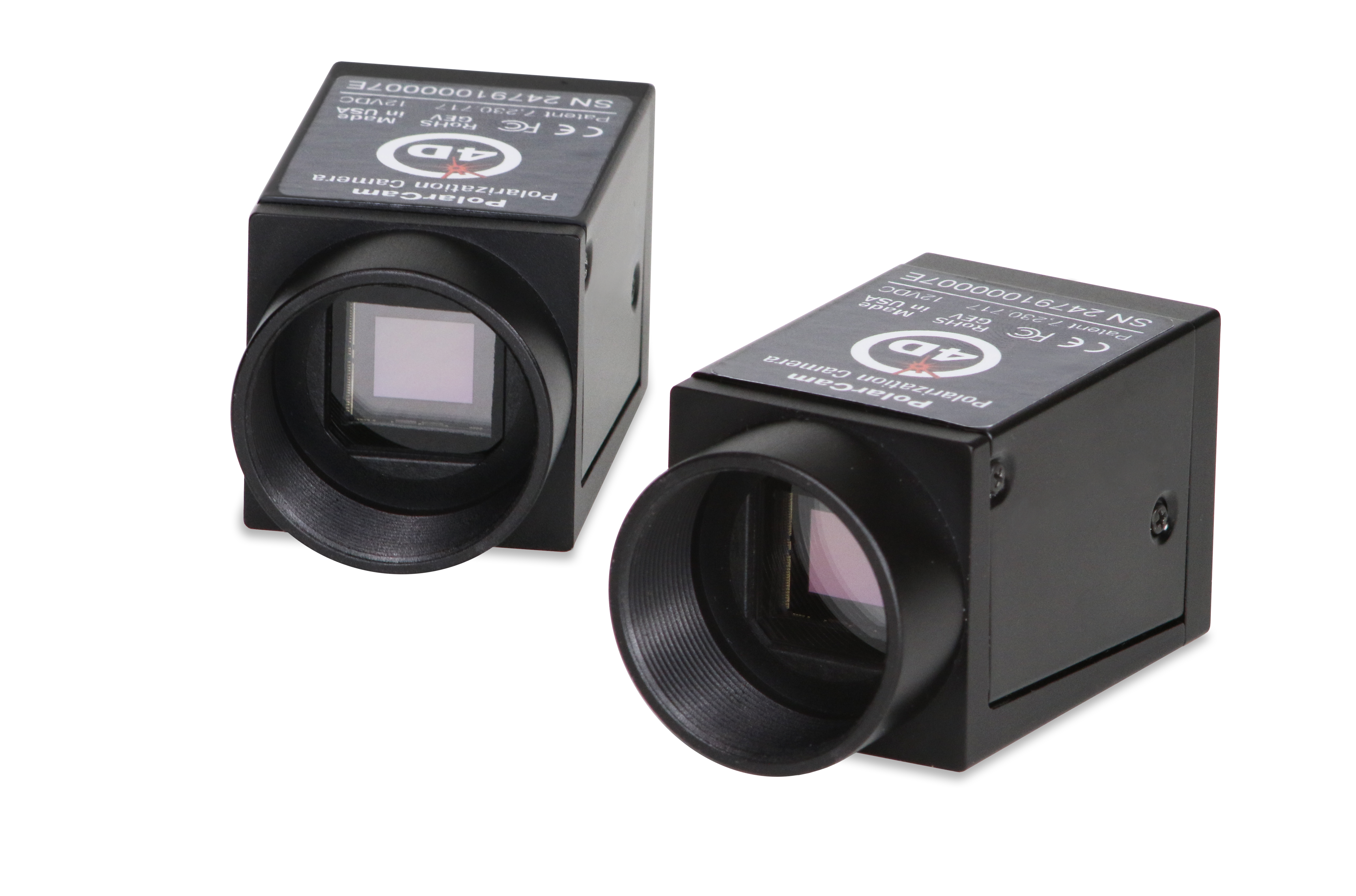
PolarCam cameras, with PolarView software, provide real-time display and calculation of key polarization parameters, including Degree of Linear Polarization (DoLP), Angle of Linear Polarization (AoLP), linear Stokes parameters (S0, S1 and S2) and more. Use the many included tools to process and analyze the data, then save images and movies of each parameter for comprehensive analysis.
Quantifying Polarization
Traditional polarimeters characterize the polarization of an imaged scene or object by capturing multiple images with a linear polarizer rotated between each image. From the captured information, one can quantify polarization parameters, such as degree of linear polarization (DoLP) and angle of linear polarization (AoLP), and amount of birefringence through a transparent material.
The Stokes vector is commonly used to describe the polarization state of a light beam. The Stokes vector is fully characterized from 6 measurements of the light beam. There are four linear polarization measurements, nominally: vertical (0°), horizontal (90°), and diagonal (45°) and diagonal (135°). And since light can also polarize in a circular way—having a clockwise twist or a counterclockwise twist—two additional circular measurements are required.
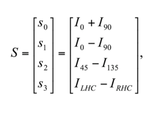
To better understand this, understand that I0 is the intensity of light reaching the sensor after passing through a linear polarizer at zero degrees (vertical), I90 is the intensity with the polarizer at 90 degrees (horizontal), I45 and I135 are intensities with the polarizer at 45 and 135 degrees, respectively. The first Stokes parameter (S0) comes from adding the horizontal and vertical intensities together, while the second parameter (S1) is the difference between the same two. The third parameter (S2) is the difference between the two diagonal intensities. The fourth Stokes parameter (S3) is the difference between the two circular polarizations.
Using linear stokes parameters
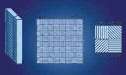
Pixelated polarization cameras like PolarCam capture the linear polarization measurements: I0, I90, I45 and I135 instantaneously in every video frame. The circular polarization components; however, cannot be captured without an externally mounted retarder plate and additional video frames. Fortunately, circularly polarized light is rare in nature and circular polarization is not required for making retardance or birefringence measurements. Furthermore, with only the linear Stokes parameters, one can generate two other useful parameters: the Degree of Linear Polarization (DoLP, i.e., the relative propensity and direction of linear polarization) and the Angle of Linear Polarization (AoLP, i.e., the angle of the polarization of the light as it reaches the imaging sensor’s plane).
Degree of Linear Polarization
DoLP is the fraction of incident light that is linear polarized. Smooth or specular surfaces tend to reflect light with high DoLP values. In outdoor scenes, most natural objects tend to be rough and are therefore characterized by low DoLP values (though water is an exception to this.) Man-made objects tend to be very smooth and are therefore characterized by high DoLP values. So DoLP can be used to highlight hidden man-made objects in natural scenes. DoLP is also useful for measuring stress-induced birefringence in transparent materials since birefringence is proportional to DoLP.
Degree of linear polarization is calculated by using the three linear Stokes parameters: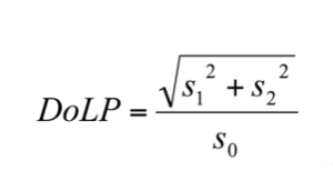
Consider the possible range of outcomes of this formula: if the difference between the intensity of vertical and horizontal polarization (S1) is a low number, and the difference between the two diagonals (S2) is a low number, then the square root in the numerator of the fraction is small—it can be as low as zero. The higher the difference in the relative intensities of either or both of Stokes S1 or S2 parameters, the larger the fraction becomes—as high as one. The squaring and square rooting operations in the numerator eliminate negative differences, so the degree of linear polarity is always a positive fraction between 0 and 1, where 1 means “completely linearly polarized,” and 0 means “devoid of linear polarization.”
AoLP is the polarization angle of the incident light relative to the camera sensor axis. The formula for calculating the Angle of Linear Polarization is simply half the arc tangent of the ratio of the intensity difference of the vertical/horizontal polarizations to the intensity difference of the two diagonal polarizations.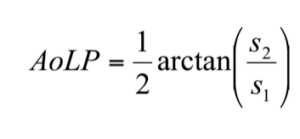
In other words, the formula calculates the polarization angle of the light as it reaches the camera sensor. This tells you, indirectly, the angle of the surface that the light reflected off of (assuming you know the incident angle of the light source). If you know the distance between the camera and the object, it’s possible to determine the 3D shape of the imaged object. This information has intriguing potential: from a single frame of polarized imagery, one could determine the 3D shape of objects in the image. Indeed, some 4D PolarCam customers are already demonstrating this capability.
Added Technical Resources
R&D subjects for polarimetry snapshot calendars
This paper presents several fields of study for which polarimeter snapshot cameras are being researched. Topics include biocellular imaging, autonomous vehicle vision, and more.
Products for Polarimetry
PolarCam Polarization Cameras
PolarCam cameras, with PolarView software, provide real-time display and calculation of key polarization parameters, including DoLP, AoLP, and linear Stokes parameters.
Do you need custom-built metrology?
Get a free consultation. 4D Technology’s mechanical, optical, electrical and software engineering teams are standing by to evaluate what it would take to meet your application’s requirements.
Get In Touch
(520) 294-5600
Location
3280 E Hemisphere Loop, Ste 146
Tucson, AZ 85706
4Dinfo@nanometrics.com
Office Hours (Arizona Time)
Mon: 8am – 5pm
Tue: 8am – 5pm
Wed: 8am – 5pm
Thur: 8am – 5pm
Fri: 8am – 5pm
Sat: Closed
Sun: Closed
Send a Message