
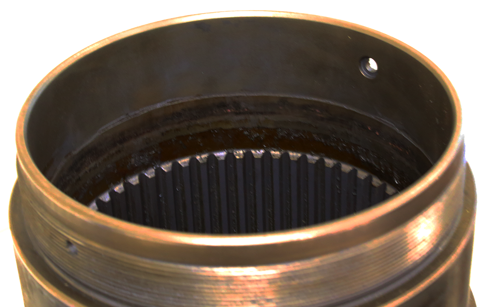
Chamfers
Chamfers are added to precision machined components for numerous reasons, including:
- to limit possible fracture points for components subject to high stresses
- to control air flow over components such as blades and nozzles
- to ensure smooth fit, especially for precision fasteners, and
- to reduce the chance of injury from sharp edges.
Measuring chamfers precisely, consistently, and quantitatively requires a capable measurement system and accurate analysis of the results.
Visual inspection of chamfers
Today, straight edge chamfers are most often qualified by visual comparison against a known angle wedge. The component is accepted or rejected based on the experienced eye of the inspector.
But visual inspection, while fast and convenient, is subject to variability in alignment, lighting, and many other factors. More importantly, a visual test provides no quantitative data. While qualitative results may be enough for some applications, they are insufficient for controlling critical components such as those used in aircraft, engines, nuclear piping, etc.
Stylus profiling is subject to variability
The most common, instrument-based method for assessing chamfers is the 2D stylus profiler. A stylus system may either be workstation-based, or it may be a portable instrument that can be placed directly on the component. While providing a fast measurement method, 2D profilers have several drawbacks:
- Measurment is only a single trace wide, providing only a minimal assessment of the surface. Further traces are required to understand the surface.
- Measurement is slow—often more than 30 minutes to achieve a single high-quality trace, and far longer to acquire multiple traces for sufficient sampling.
- Results are susceptible to variation in the measurement angle relative to the part.
- Limited vertical range prevents measurement of larger chamfers.
This combination of limitations means that multiple measurements—or, in critical applications, multiple inspectors—are required to get enough data to properly assess chamfers.
3D optical measurement provides quantitative production data
Precision machined part manufacturers rely on non-contact, 3D optical metrology to quantify chamfer geometries. 3D optical measurement provides quantitative results, reduces measurement time, and improves accuracy and repeatability. It also eliminates the alignment errors that hamper stylus-based measurements.
Traditionally, optical measurement systems have required vibration control and isolation in metrology labs, limiting their effectiveness for shop floor measurement of larger components. These systems also tend to be expensive and require a steep learning curve to use.
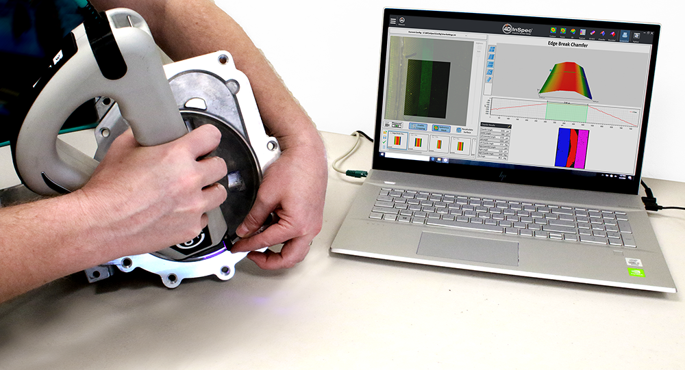
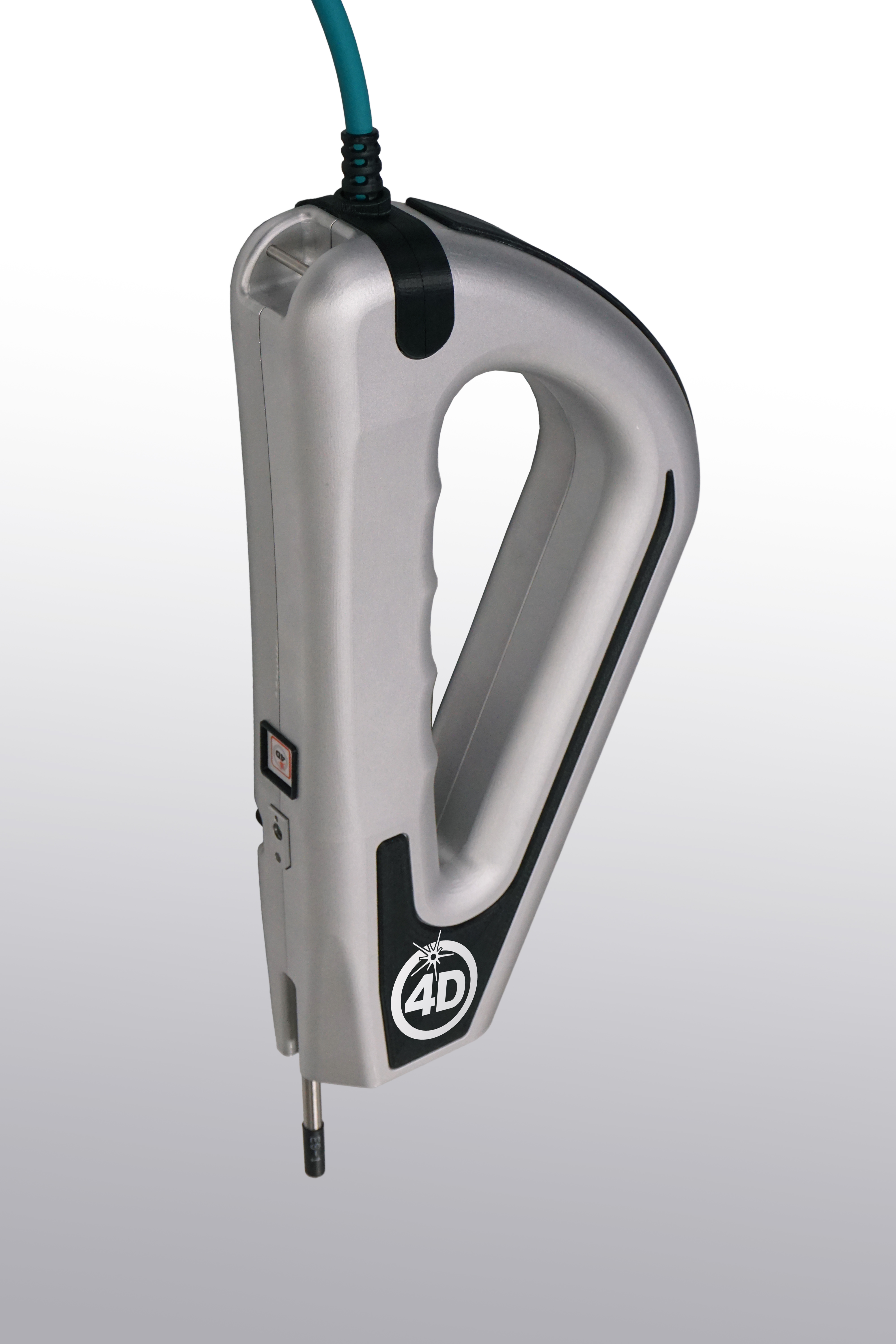
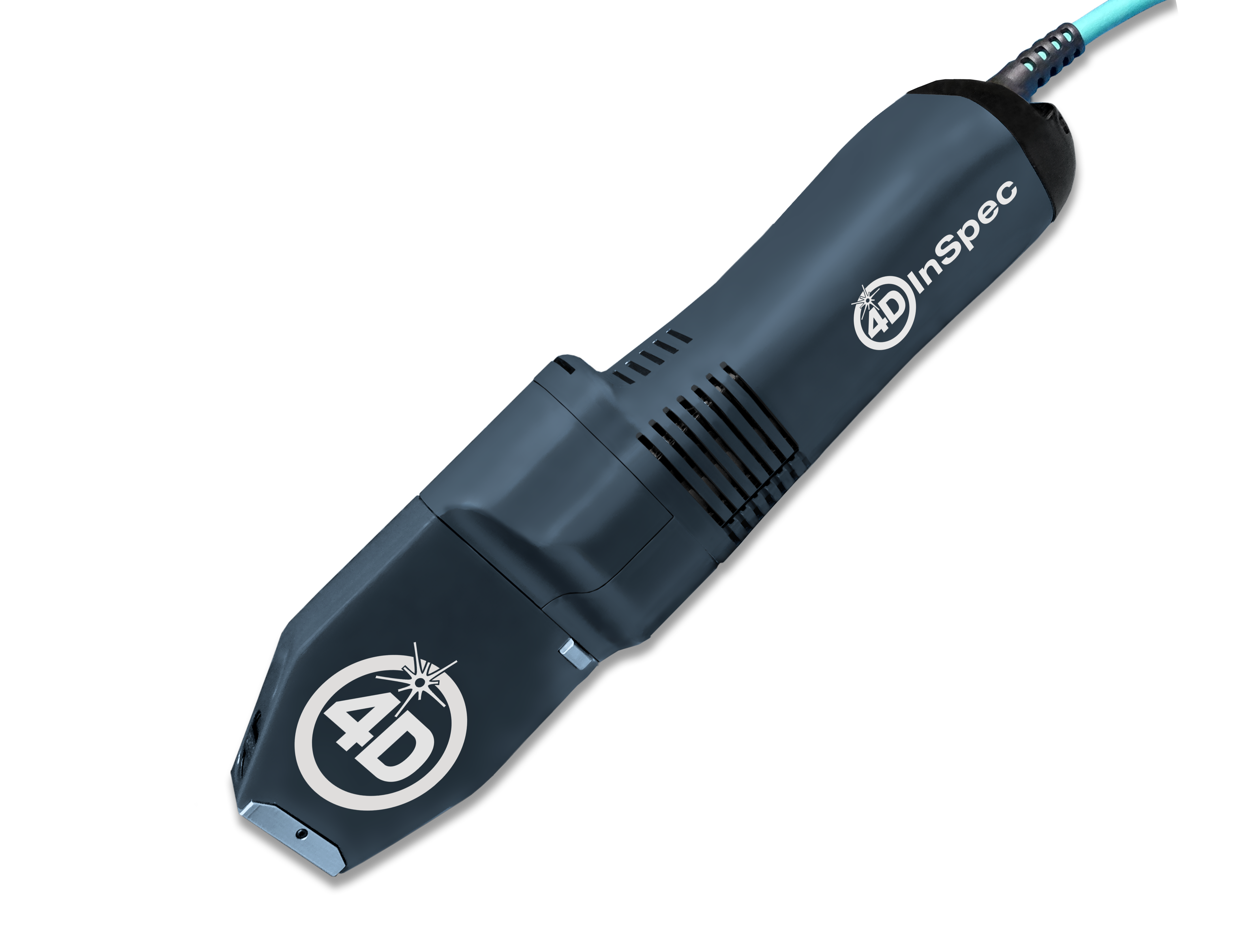
4D Technology’s 4D InSpec Surface Gauge, however, is a handheld, 3D measurement device for rapid, simple measurement of chamfers and other precision part geometries. The 4D InSpec is designed for shop floor measurement, providing repeatability, reproducibility, ruggedness and ease-of-use for measuring chamfers in production and in repair/overhaul facilities.
4D InSpec’s unique visualization system is able to measure on virtually any material. Its compact design allows measurement in tight corners, inside bores, and over large surfaces.
Video: Measuring Chamfers and Edge Radius with 4D InSpec
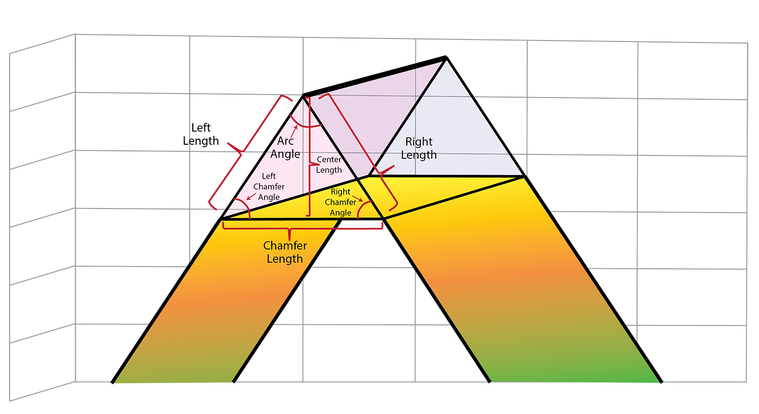
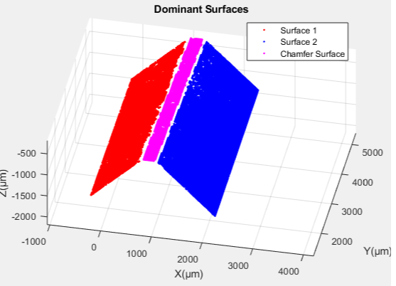
Calculating chamfer geometries
One major advantage of 3D measurement is the ability to calculate geometries based on best-fit planes, rather than from single traces. This added robustness greatly improves repeatability, by removing alignment variability from the equation. Chamfer size, angles, and other data are rapidly acquired from a single measurement.
The 4D InSpec uses Polarized Structured Light, a measurement technique with vertical resolution better than 2 micrometers over a 2.5mm vertical range. The 4D InSpec therefore provides sufficient resolution for gauge-capable measurement of chamfers on most precision machined parts, which typically require tolerances of 150-300 micrometers.
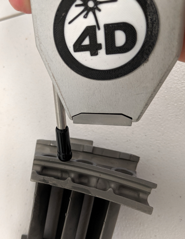
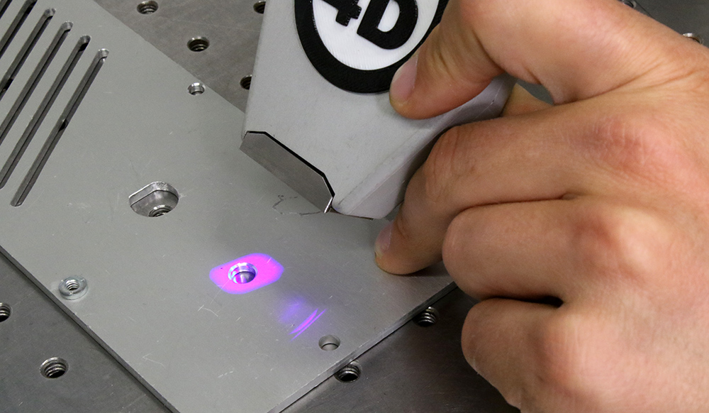
In this image the 4D InSpec is being used to measure the chamfer at the top of a through hole.
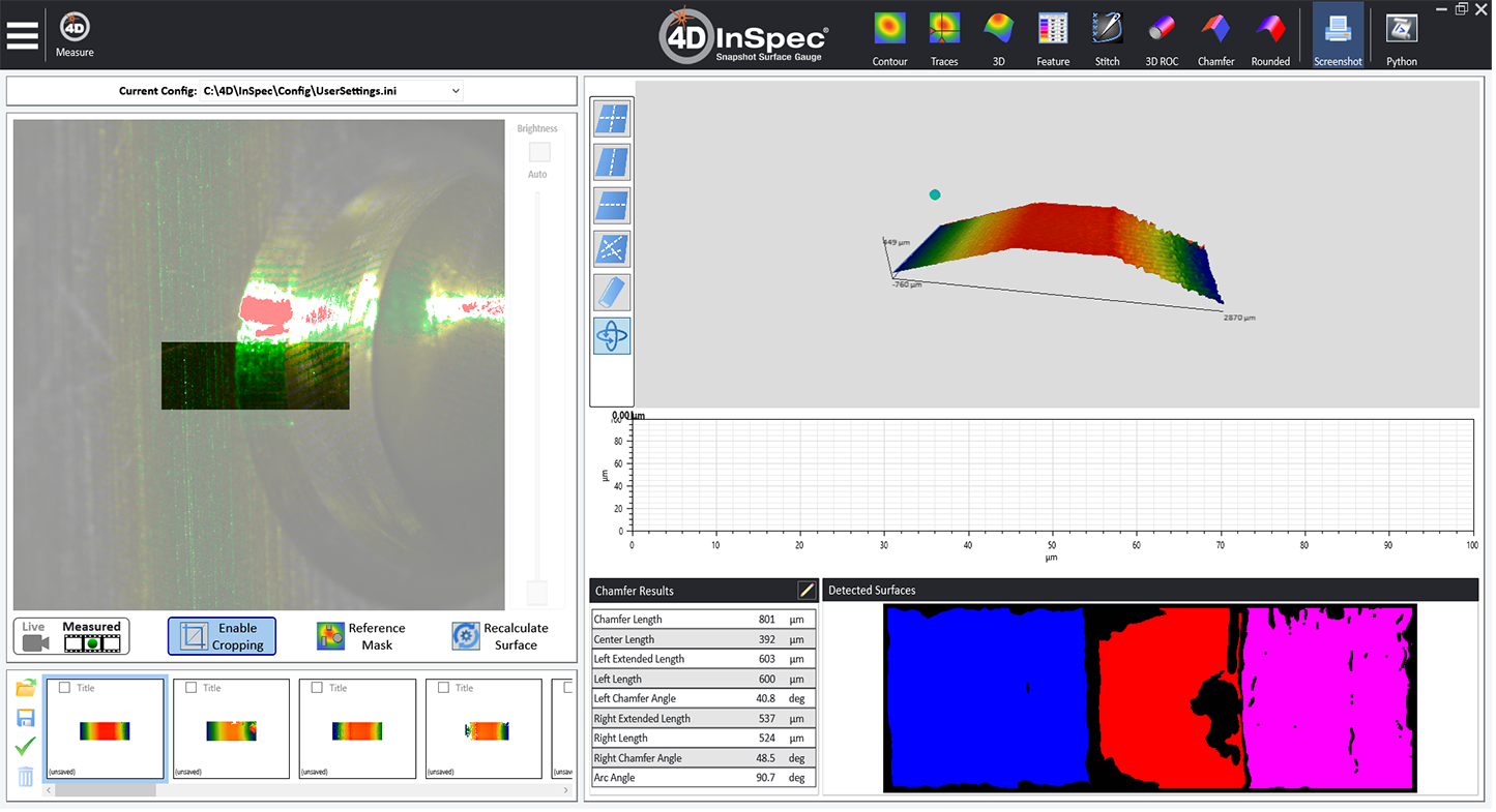
Here is the resulting data as shown in the 4D InSpec software.
4D InSpec XL
For larger measurements, the 4D InSpec XL provides the same, micrometer-level resolution, portability and ease-of-use but with a larger field of view and higher scan range. Measure features up to 0.6″ x 0.6″ across and report results in about a second.
Added Technical Resources
3D Shop Floor Characterization of Radii and Chamfers
A published scientific paper on measuring edge break and chamfers using 4D InSpec.
Learn more about the products
4D InSpec
4D InSpec provides non-contact measurement of surface features and defects, on the factory floor, in machine shops and in field service applications.
4D InSpec XL
A handheld defect inspection gauge that works like 4D InSpec standard, but with a larger field of view, to measure wider and deeper features.
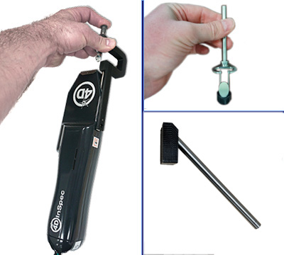
InSpec Accessories
Accessories for improving portability, ease of use, or for accessing hard to reach measurements like sidewalls and through-holes.
Get In Touch
(520) 294-5600
Location
3280 E Hemisphere Loop, Ste 146
Tucson, AZ 85706
4Dinfo@ontoinnovation.com
Office Hours (Arizona Time)
Mon: 8am – 5pm
Tue: 8am – 5pm
Wed: 8am – 5pm
Thur: 8am – 5pm
Fri: 8am – 5pm
Sat: Closed
Sun: Closed
Send a Message